User Manual for Automatic Elevator
1、 Main parts introduction:
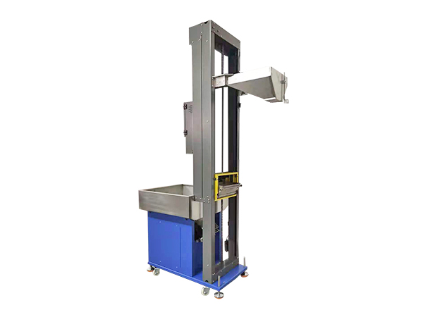
1. Storage bin 2. Electric control box 3. Discharge hopper 4. Up travel switch 5. Photoelectric sensing assembly 6. Lifting frame 7. Loading box 8. Down travel switch 9. Vibration discharge assembly
2、 Power supply and external dimensions:
YL18040 W52XL78XH180CM; YL21040 W52XL78XH210CM;
YL18050 W65XL98XH180CM; YL21050 W65XL98XH210CM;
YL22650 W65XL98XH240CM; YL25150 W65XL98XH260CM;
3. Increase height:
YL1840/YL1850: 1.0-1.4M; YL2140/YL2150: 1.4-1.7M;
YL22650: 1.5-1.9M YL25150: 1.7-2.15M
3、 Function Introduction
1. Pour the product into the storage bin, connect the power, turn on the emergency stop switch, and turn on the power.
2. Press the start switch, and the motor will drive the transmission assembly in reverse to lower the lifting frame to the lower limit position.
3. The lower limiter is connected to send a signal to the PLC, which starts the direct vibration switch to drive the vibration discharge assembly to vibrate, causing the product to flow from the vibration discharge assembly into the loading box inside the lifting frame. During this process, the time controller counts down, and the direct vibration stops after the time controller returns to zero.
4. After receiving the signal from the time controller, the PLC drives the motor forward to drive the transmission assembly to lift the lifting frame upward until it reaches the upper limit position. The upper limit position is connected to send a signal to the PLC, which controls the motor to stop for 2 seconds and then reverse to drive the lifting frame down to the lower limit position; Loop through steps 3 and 4 to achieve multiple small batch product additions.
When the lifting frame rises to the fixed position of the feeding hopper, the feeding device guides the feeding box inside the lifting frame to tilt, achieving feeding and allowing the product to slide into the vibrating plate along the feeding hopper.
When the photoelectric sensing assembly senses, the green light of the start button for normal machine operation remains on; When there is no response, the machine stops waiting and the green light of the start button flashes.
When there is no signal output from the photoelectric induction for a long time, the machine will run up and down continuously for 5 times, and the machine will automatically stop waiting and start the fail safe mode; To prevent excessive product accumulation caused by continuous operation of the machine, ultimately achieving unmanned night shifts.
8. Press the emergency stop switch, and the machine will automatically shut down.
9. Jogging mode: When the red light of the stop switch lights up and the photoelectric sensing assembly senses, press and hold the stop switch for 5 seconds to lift the frame upwards. Conversely, when the photoelectric sensing assembly does not sense, press and hold the stop switch for 5 seconds to lift the frame downwards. Release the button to stop the action.
10. The motor speed is controlled by the rotary switch on the motor speed controller, which can be turned on 60-80 under normal circumstances.
11. Vibration controller, which can adjust the force of the vibration discharge assembly and control it within 15-25 under half wave conditions.
4、 Common fault handling
1. If the red light on the stop switch flashes, it indicates that the motor is overloaded and the lifting frame needs to be checked for any jamming; If it is not stuck, it means that the product in the loading box is too heavy, exceeding the carrying capacity of the motor.
2. Lift the frame to the top, but the products in the loading box are not clean. It is necessary to adjust the position of the up travel switch and move it up by 3-5mm. If the lifting frame reaches the top and there is interference or jamming between the edge of the loading box and the edge of the feeding hopper, the up travel switch should be moved downwards to 3-5mm.
3. The products in the discharge port flap cannot be completely dropped. Check if the loading box is already full. If not, adjust the downward travel switch by 3-5mm to tilt the discharge port flap downward by 20 degrees; If it is already full, adjust the height of the discharge port baffle to prevent too many products from being discharged each time. The height of the discharge port baffle should be normal for 1-2 products. If the height of the product is greater than the adjustable height of the discharge port baffle, the discharge port baffle can also be removed without using it.
4. If the lifting frame stops at a certain position without getting stuck, it indicates that one of the travel switches has not returned to its original position. It is necessary to manually try whether the travel can return to its original position normally.
5. After running the machine several times and waiting for it to stop, check if the proximity switch on the photoelectric induction assembly is sensing. If it is sensing, it means that the foolproof mode is working. If not, you can adjust the screw below the proximity switch upwards to create a 2mm gap between the top of the screw and the bottom of the proximity switch. If the gap is too large, it will not be sensed, and if it is too small, it will affect its activity space.
6. When powered on, the machine runs out of power and all indicator lights do not light up; The fuse is blown. There is a fuse at the external power supply of the electrical control box, and there is also a fuse on the circuit board. Just check and replace the 3-5A fuse.


 Chinese Version
 English version